motor control type C-1
https://mhc.andornot.com/en/permalink/artifact484
- Dates
- 1970
- 1990
- circa 1970-1990
- Collection
- Queen's University School of X-Ray Collection
- Category
- Diagnostic & Treatment Artifacts
- Classification
- Radiotherapy
- Accession Number
- 995004068
- Description
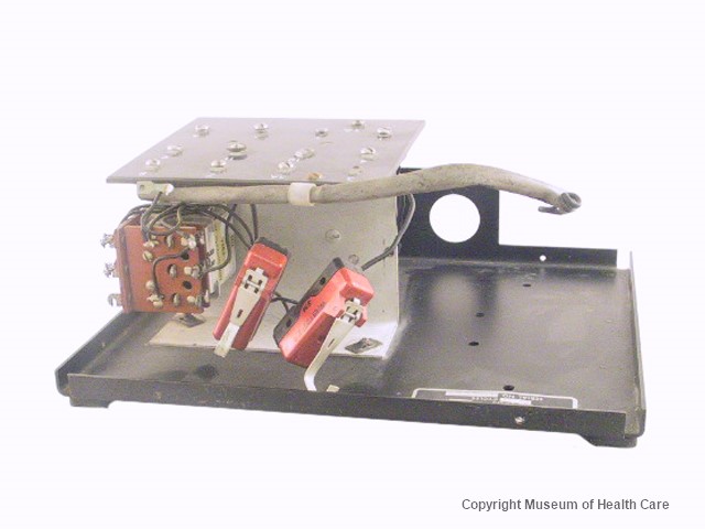
- Dynamax motor controller which consists of a flat metal base with turned-up edges and a high piece at the front centre edge; set onto the base is a unit with 31 black plastic-coated wires connecting two limit switches and relays which are screwed into coated wooden pieces; on top of this is a black…
2 images
- Accession Number
- 995004068
- Category
- Diagnostic & Treatment Artifacts
- Classification
- Radiotherapy
- Description
- Dynamax motor controller which consists of a flat metal base with turned-up edges and a high piece at the front centre edge; set onto the base is a unit with 31 black plastic-coated wires connecting two limit switches and relays which are screwed into coated wooden pieces; on top of this is a black plastic flat top with 15 screws (two missing); these are numbered "3, 3A, 7, 8, 4, 10, 11, 9, 1, 2, 5, 6, 1A"
- Number Of Parts
- 1
- Provenance
- Queen's University School of X-Ray.
- Maker
- Dynamax
- Dates
- 1970
- 1990
- circa 1970-1990
- Material
- metal: silver; black
- plastic: red; black
- wood: brown
- Inscriptions
- Manufacturer's label reads: "Dynamax Motor Control Type C-1 Time Delay 1.0 sec 105/125 Volts 125 250V AC WHBI21-1 SM"; and "Und. Lab. Inc. Insp. 20A, 125, 250, 480 V, AC 0.25A, 250V DC 0.50A, 125V, DC 2HBI-1 SM"; bottom has serial number "A-34241"
- Permanent Location
- Storage Room 0010
- 0010-F3-12
- Dimension Notes
- Length: 25.4 cm. x Width: 20.9 cm. x Depth: 10.0 cm.
- Condition Remarks
- The motor control was very dirty and dusty
- Copy Type
- Original
- Reference Types
- Person
- Reference Comments
- Bernie Ziomkiewicz
- Research Facts
- The red and black plastic switches are limit switches which will stop the motor; there is a time delay feature; relays control large voltage or current; possibly used with a radiation therapy unit of some kind
Images